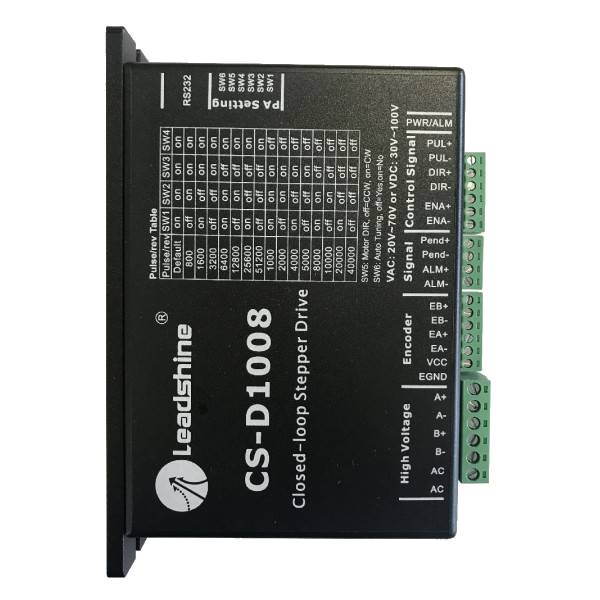
CS-D1008closed loop servo driver 70V AC / 100V DC 8A
Closed loop servo motor Driver
- 2 phase
- 20-70 VAC or 30-100 VDC 8A
- Pulses/Dir or CW/CCW
- CE certified and ROHS compliant
Internal Reference:
CS-D1008
- Pulses/Dir or CW/CCW drive modes
- Power supply 20-80 VAC or 20-100 VDC, for a max. of 8.0A
- suitable for 2-phase NEMA 23, 24, 34, or 42 stepper motors equipped with a 1000-point encoder
- Closed loop, eliminates step loss
- No hunting
- Fast response without overshoot, jerk or oscillation
- Needless Torque margin
- Reduced heating and better performance
- Mouvements souples et très silencieux
- CE certification, RoHS compliant
The Leadshine CS-D1008 driver is a new generation stepper motor driver.
It operates in a closed loop and therefore provides real-time position feedback with 2-phase stepper motors equipped with encoders (NEMA size 34).
This solution combines the advantages of stepper motors and servomotors thanks to the management of encoders integrated into the motors.
The control interface is similar to that of a classic stepper motor driver. Since the encoder is managed directly by the driver, it can return an error signal to you in the event of a mechanical blockage (configurable tolerance window).
This solution therefore provides the positioning reliability of a servomotor but also great simplicity of implementation.
| CS-D1008 | ||||
|---|---|---|---|---|
| Parameters | Min | Typical | Max | Unit |
| Output current | 0.5 | 20 | 8.0 (Peak) | A |
| Operating Voltage DC | 30 | 48 ~60 | 80 | VDC |
| Operating Voltage AC | 20 | - | 100 | |
| Logic signal current | 7 | 10 | 16 | mA |
| Pulse input frequency | 0 | 20 | 200 | kHz |
| Minimal pulse width | 2.5 | 20 | 20 | μS |
| Minimal direction setup | 5 | 20 | 20 | μS |
| Insulation resistance | 500 | MΩ |
| Pin Assignments of P1 & P2 connectors | |||
|---|---|---|---|
| Pin | Name | I/O | Description |
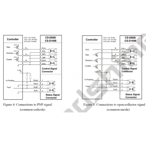
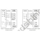
| 1 | PUL+ | I | Pulse signal: (1). In single pulse (pulse & direction) control mode, this input represents pulse signal. A pulse signal is active at the rising or falling voltage edge (set by PC software). (2). In double-pulse (CW/CCW) control mode (set by PC software), this signal input represents clockwise (CW) pulse, and is active at both high voltage level and low voltage level. (3). 4.5-24V for voltage HIGH, 0-0.5V for voltage LOW (same for DIR and ENA signals). (4). Pulse width should be set to 2.5μs or longer. |
| 2 | PUL- | I | |
| 3 | DIR+ | I | Direction Signal:(1). In single pulse (step & direction) control mode, this signal’s low and high voltage levels represent the two directions of motor rotation (e.g. clockwise and counterclockwise). (2). In double-pulse (CW & CCW) control mode, this signal represents counterclockwise (CCW) rotation. It is active at both voltage high level and low level. (3). Minimal DIR signal setup time should be at least 5μs. (4). Rotation direction is related to your motor/drive wiring. You can reverse the default rotation direction by toggling the SW5 DIP switch. |
| 4 | DIR- | I | |
| 5 | ENA+ | I | Enable signal: This signal is used for enabling/disabling the drive. High voltage level of 4.5-24V (NPN control signal) for enabling the drive and low voltage level of 0-0.5VDC for disabling the drive. PNP and Differential control signals are on the contrary, namely Low level for enabling. By default this signal is left UNCONNECTED & ENABLED. |
| 6 | ENA- | I | |
| 7 | Pend+ | o | In-position Signal: OC output signal, active when the difference between the actual position and the command position is zero. This port can sink or source 20mA current at 24V. The resistance between Pend+ and Pend- is active at high impedance. |
| 8 | Pend- | o | |
| 9 | ALM+ | o | Fault Signal: An OC output signal which is active when one of the following error protection is activated: over-voltage, over-current, and position following error. This port can sink or source 20mA current at 24V. The resistance between ALM+ and ALM- is low impedance in normal operation, and will change to high when the drive goes into error protection. The voltage active level of this false output signal can be configured by configuration software. |
| 10 | ALM- | o |
| P3 connector - Encoder connection | ||
|---|---|---|
| Pin | Name | Description |
| 1 | EB+ | Encoder B+ input connection |
| 2 | EB- | Encoder B- input connection |
| 3 | EA+ | Encoder A+ input connection |
| 4 | EA- | Encoder A- input connection |
| 5 | VCC | Encoder +5V voltage output connection |
| 6 | EGND | Power ground connection |
| P4 connector - Motor and Power Supply connection | ||
|---|---|---|
| Pin | Name | Details |
| 1 | A+ | Stepper motor A+ connection. Connect motor A+ wire to this pin |
| 2 | A- | Stepper motor A- connection. Connect motor A- wire to this pin |
| 3 | B+ | Stepper motor B+ connection. Connect motor B+ wire to this pin |
| 4 | B- | Stepper motor B- connection. Connect motor B- wire to this pin |
| 5 | AC | Power supply positive connection. 30-100VDC or 20-70VAC power supply voltage |
| 6 | AC |
| RS232 communication port – RJ11 | |||
|---|---|---|---|
| Pin | Name | I/O | Description |
| 1 | NC | 20 | Not connected |
| 2 | +5V | O | +5V power output |
| 3 | TxD | O | RS232 transmit |
| 4 | GND | GND | Ground |
| 5 | RxD | I | RS232 receive |
| 6 | NC | 20 | Not connected |
Accessories
Specifications
| Brand | Leadshine |
| Min. Voltage | 24 V |
| Max. Voltage | 100 V |
| Max. current | 8 A |
| Resolution setting | DIP-switches |
| Configurable | via RS232 cable |
| Current setting | Tuning software |