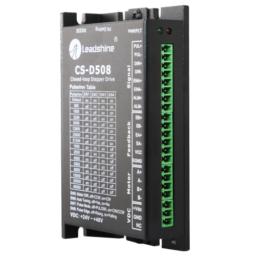
CS-D508 closed loop servo driver 50V/8A
Hybrid Servo Motor Driver
- 2 phase
- 50V 8A
- Pulses/Dir or CW/CCW
- CE certified and ROHS compliant
Product Documents
Internal Reference:
CS-D508
- Step & direction or CW/CCW control modes
- Supply voltage of 20-50 VDC, maximum output current of 8.0A
- Powering 2-phase stepper motors of NEMA 8, 11, 14, 17, 23, and 24
- Fault output, brake control, or in-position output.
- No lose of steps for closed position loop
- No hunting, no overshooting
- No torque margin
- Reduced motor heating and more efficient
- Smooth motion and super-low motor noise
- CE certified and RoHS compliant
The Leadshine CS-D508 driver is a new generation stepper motor driver.
It operates in a closed loop and therefore provides real-time position feedback with 2-phase stepper motors equipped with encoders.
This solution combines the advantages of stepper motors and servomotors thanks to the management of encoders integrated into the motors.
The control interface is similar to that of a classic stepper motor driver. Since the encoder is managed directly by the driver, it can return an error signal to you in the event of a mechanical blockage (configurable tolerance window).
This solution therefore provides the positioning reliability of a servomotor but also great simplicity of implementation.
| CS-D508 | ||||
|---|---|---|---|---|
| Parameters | Min | Typical | Max | Unit |
| Output current | 0,5 | - | 8,0(Pointe) | A |
| Operating voltage | 30 | 24 ~ 48 | 50 | VDC |
| Logic signal current | 7 | 10 | 16 | mA |
| Pulse input frequency | 0 | - | 200 | kHz |
| Minimum pulse width | 2,5 | - | - | μS |
| Minimal direction setup | 5 | - | - | μS |
| Insulation resistance | 500 | MΩ |
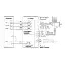
| Pin Assignments of P1 & P2 | |||
|---|---|---|---|
| Pin | Name | I/O | Description |
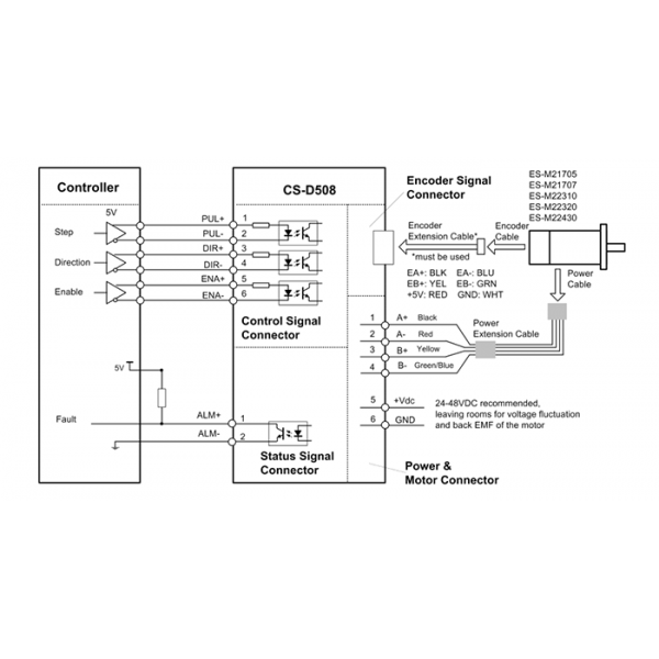
| 1 | PUL+ | I | Pulse signal: In single pulse (pulse & direction) control mode, this input represents pulse signal. A pulse signal is active at the rising or falling voltage edge (set by switch SW7). In double-pulse (CW/CCW) control mode (set by PC software), this signal input represents clockwise (CW) pulse, and is active at both high voltage level and low voltage level. 4.5-5V for voltage HIGH, 0-0.5V for voltage LOW (same for DIR and ENA signals). Pulse width should be set to 2.5μs or longer. |
| 2 | PUL- | I | |
| 3 | DIR+ | I | Direction Signal: In single pulse (step & direction) control mode, this signal’s low and high voltage levels represent the two directions of motor rotation (e.g. clockwise and counterclockwise). In double-pulse (CW & CCW) control mode, this signal represents counterclockwise (CCW) rotation. It is active at both voltage high level and low level. Minimal DIR signal setup time should be at least 5μs. Rotation direction is related to your motor/drive wiring. You can reverse the default rotation direction by toggling the SW5 DIP switch. . |
| 4 | DIR- | I | |
| 5 | ENA+ | I | Entrée Enable : cette entrée sert à activer/désactiver
le driver. Par défaut, si cette entrée est inutilisée, le driver est
activé. La mise a l'état HAUT de cette entrée désactive le driver. Niveaux BAS : 0-0.5V, HAUT : 4.5-5V Cette commande peut être inversée par soft (réglable par le logiciel). Elle peut également être utilisée pour effacer une alarme (réglable par le logiciel). |
| 6 | ENA- | I | |
| 7 | ALM+ | O | Fault Signal: An OC output signal which is active when one of the following error protection is activated: over-voltage, over-current, and position following error. This port can sink or source 20mA current at 24V. The resistance between ALM+ and ALM- is low impedance in normal operation, and will change to high when the drive goes into error protection. The voltage active level of this false output signal can be configured by configuration software. |
| 8 | ALM- | O |
| Connector P3 - Encoder Connection | ||
|---|---|---|
| Pin | Name | Description |
| 1 | EB+ | Encoder B+ input connection |
| 2 | EB- | Encoder B- input connection |
| 3 | EA+ | Encoder A+ input connection |
| 4 | EA- | Encoder A- input connection |
| 5 | VCC | Power supply positive connection. 30-80VDC power supply voltage |
| 6 | EGND | Power supply ground connection. |
| Connector P4 - Motor and Power Supply Connection | ||
|---|---|---|
| Pin | Name | Details |
| 1 | A+ | Stepper motor A+ connection. Connect motor A+ wire to this pin |
| 2 | A- | Stepper motor A- connection. Connect motor A- wire to this pin |
| 3 | B+ | Stepper motor B+ connection. Connect motor B+ wire to this pin |
| 4 | B- | Stepper motor B- connection. Connect motor B- wire to this pin |
| 5 | +Vdc | Power supply positive connection. 30-80VDC power supply voltage |
| 6 | GND | Power supply ground connection. |
| RS232 Communication Port – RJ11 | |||
|---|---|---|---|
| Pin | Name | I/O | Description |
| 1 | NC | - | Not connected |
| 2 | +5V | O | +5V power output |
| 3 | TxD | O | RS232 transmit |
| 4 | GND | GND | Ground |
| 5 | RxD | I | RS232 receive |
| 6 | NC | - | Not connected |
Accessories
Specifications
| Brand | Leadshine |
| Min. Voltage | 24 V |
| Max. Voltage | 50 V |
| Max. current | 8 A |
| Resolution setting | DIP-switches |
| Configurable | via RS232 cable |
| Current setting | Tuning software |