| |
Features
|
 |
-
Patented Technology
- Low cost
- High torque, even at high speed
-
Input voltage 20-48VDC
, Peak current 4.2A max (3A RMS)
- 3-state current control technology
-
Automatic idle-current reduction (configurable)
- For use with 2 or 4 phases motors (unipolar or bipolar)
- Opto-isolated input signals
-
Pulse input frequency up to
400 KHz
-
15 selectable micro-step resolutions of 400-25,000 via DIP switches
-
8 selectable output current settings of 1A to 4.2A via DIP switches
- Configurable mode: PULSE/DIRECTION or CW/CCW
- Short circuit, over voltage and under voltage protection
- Contained dimension (118x75.5x33mm)
- Pluggable connectors
|
|
Introduction
|
|
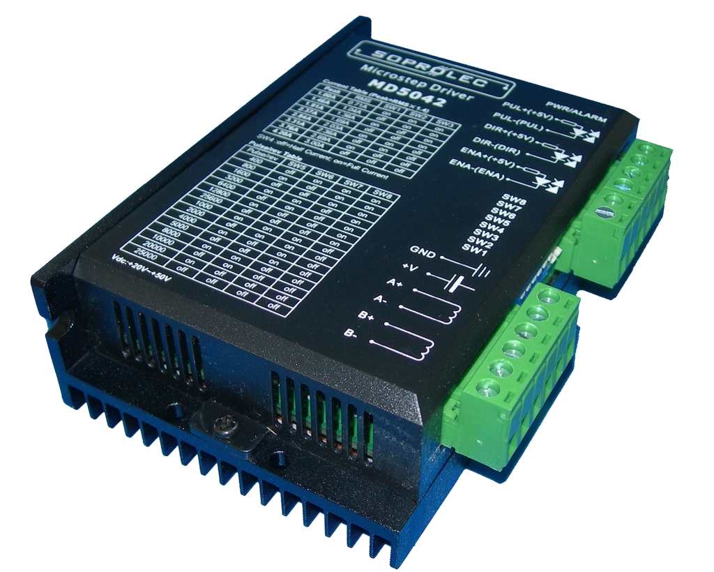
The MD5042 is a high performance microstepping driver using the most modern technologies. It can be used to drive 2-phase or 4-phase hybrid stepper motors (bipolar or unipolar). Thanks to an advanced technique of constant current management, it is possible to make the best use of the characteristics of your motors. The 3-state current control technology allows precise control of the current in the motor windings with low ripple and therefore less heating.
|
Applications
|
|
Utilisable avec une large gamme de moteurs pas à pas Nema 17 et 23,
et pour différents types d'application tel que des tables XY, des
machines de marquage, de découpe laser, de gravure ou des machines de
placement. Particulièrement recommandé pour des applications nécessitant
de faibles vibrations, des vitesses élevées et de la précision.
|
Electrical specifications
(Tj=25℃) |
|
Parameter
|
MD5042
|
| |
Mini
|
Typical
|
Max
|
|
Output current
|
0.54
|
-
|
4.2 (3A RMS)
|
Amps
|
|
Voltage (DC)
|
20
|
36
|
50
|
VDC
|
|
Current logic signals
|
7
|
10
|
16
|
mA
|
|
Input signal frequency
|
0
|
-
|
300
|
Khz
|
|
Insulation resistance
|
500
|
-
|
-
|
MΩ
|
|
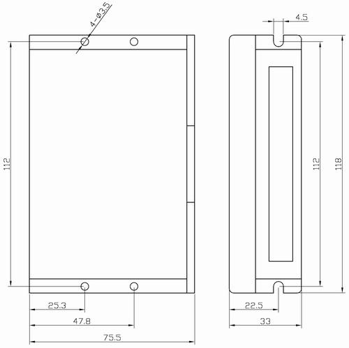
| Mechanical specifications (Unit: mm, 1 inch=2.54 mm) |
|
|
Description of connectors
|
P1 Command
connector
|
Pin Function
|
Details
|
|
PUL﹢(+5V)
|
Pulse inputs: In PULSE/DIRECTION mode, each rising edge on this input causes a step forward. Depending on the application of the signal to the PUL+ or PUL- input, the input will be active from 4 to 5V or from 0 to 0.5V. In CW/CCW mode, the input is used to advance one step in the CW direction. The minimum pulse duration is 1.5µs. For use with control signals greater than 5V, an additional series resistor is required.
|
|
PUL- (PUL)
|
|
DIR+ (+5V)
|
DIR input: In PULSE/DIR mode, this input is used to select the direction of rotation. In CW/CCW mode (mode configuration by jumper J3 in the case), the input is used to advance one step in the CCW direction. To ensure quality movements, a change of direction must be followed by a delay of at least 5µs before sending pulses.
|
|
DIR- (DIR)
|
|
ENA+ (+5V)
|
Enable input: This input is used to activate / deactivate the motor supply. At + 5V, the power is activated. At 0V, the power is deactivated. If this input is not connected, power is activated.
|
|
ENA- (ENA)
|
Note: drivers are set to PULSE/DIRECTION mode by default.
P2 power connector
|
Pin Fonction
|
Détails
|
|
Gnd
|
Ground DC
|
|
+V
|
Motor power DC, +20VDC to +50VDC.
|
|
Phase A
|
Motor coil A (fil A+ et A-)
|
|
Phase B
|
Motor coil B (fil B+ et B-)
|
|
|
Microstep resolution selection :
|
|
Microstep resolution selection is selected by DIP Switches 5, 6, 7, and 8 as follow:
| Microstep |
usteps/rev.( 1.8°/rev) |
SW5 |
SW6 |
SW7 |
SW8 |
| 2 |
400 |
OFF |
ON |
ON |
ON |
| 4 |
800 |
ON |
OFF |
ON |
ON |
| 8 |
1600 |
OFF |
OFF |
ON |
ON |
| 16 |
3200 |
ON |
ON |
OFF |
ON |
| 32 |
6400 |
OFF |
ON |
OFF |
ON |
| 64 |
12800 |
ON |
OFF |
OFF |
ON |
| 128 |
25600 |
OFF |
OFF |
OFF |
ON |
| 5 |
1000 |
ON |
ON |
ON |
OFF |
| 10 |
2000 |
OFF |
ON |
ON |
OFF |
| 20 |
4000 |
ON |
OFF |
ON |
OFF |
| 25 |
5000 |
OFF |
OFF |
ON |
OFF |
| 40 |
8000 |
ON |
ON |
OFF |
OFF |
| 50 |
10000 |
OFF |
ON |
OFF |
OFF |
| 100 |
20000 |
ON |
OFF |
OFF |
OFF |
| 125 |
25000 |
OFF |
OFF |
OFF |
OFF |
|
|
Current setting
|
| Peak Current (A) |
RMS (A) |
SW1 |
SW2 |
SW3 |
| 1.0 |
0.71 |
ON |
ON |
ON |
| 1.46 |
1.04 |
OFF |
ON |
ON |
| 1.91 |
1.36 |
ON |
OFF |
ON |
| 2.37 |
1.69 |
OFF |
OFF |
ON |
| 2.84 |
2.03 |
ON |
ON |
OFF |
| 3.31 |
2.36 |
OFF |
ON |
OFF |
| 3.76 |
2.69 |
ON |
OFF |
OFF |
| 4.20 |
3.00 |
OFF |
OFF |
OFF |
SW4 set to OFF :
current is reduced by 60% one second after motor stops.
SW4 set to ON :
current is always as set.
|
Typical wiring:
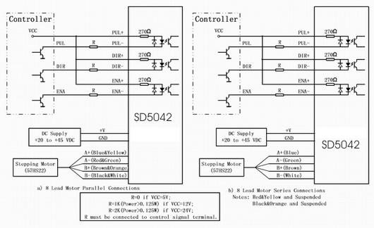
|