DMD4022 Digital Microstep driver 40V/2.2A
Stepper Motor Driver
Power supply 20 to 40V max
Output current 2.2A (1.6A RMS) selectable in 8 ratings
Dimensions 86 x 55 x 25.5mm
Pulse commands up to 75KHz
Resolution from 1600 to 6400 pulses/turn (on 4 calibres)
Automatic current reduction at standstill,
Over voltage and overload protection.
Internal Reference:
DMD4022
DMD4022 Digital Microstep Driver
|
||||||||||||||||||||||||||||||||||||
Introduction |
||||||||||||||||||||||||||||||||||||
|
The DMD4022 is a versatile fully digital stepping driver based on a DSP with advanced control algorithm. The DMD4022 is the next generation of digital stepping motor controls. It brings a unique level of system smoothness, providing optimum torque and nulls mid-range instability. Motor self-test and parameter auto-setup technology offers optimum responses with different motors and easy-to-use. The driven motors can run with much smaller noise, lower heating, smoother movement than most of the drivers in the markets. Its unique features make the DMD4022 an ideal solution for applications that require low-speed smoothness. The user can configure the standstill current in the software. What’s more, a pulse filter (smoother) has been built into the DMD4022. The DMD4022 driver is a fully digital driver based on DSP technology with advanced regulation algorithms. It is part of the new generation of microstep drivers offered by SOPROLEC. This new technology optimizes rotational fluidity while reducing heating and eliminating resonance associated with stepper motor technology. The driver has an auto-setup function allowing the automatic optimization of the regulation parameters. |
||||||||||||||||||||||||||||||||||||
Applications |
||||||||||||||||||||||||||||||||||||
|
Suitable for a wide range of stepping motors, from NEMA frame size 14 to 23. It can be used in various kinds of machines, such as laser cutters, laser markers, high precision X-Y tables, labeling machines, and so on. Its unique features make the DMD4022 an ideal solution for applications that require low-speed smoothness. Serial link tuning allows to adjust the settings of the driver in an optimum way. |
||||||||||||||||||||||||||||||||||||
Electrical specifications (Tj=25℃) |
||||||||||||||||||||||||||||||||||||
|
||||||||||||||||||||||||||||||||||||
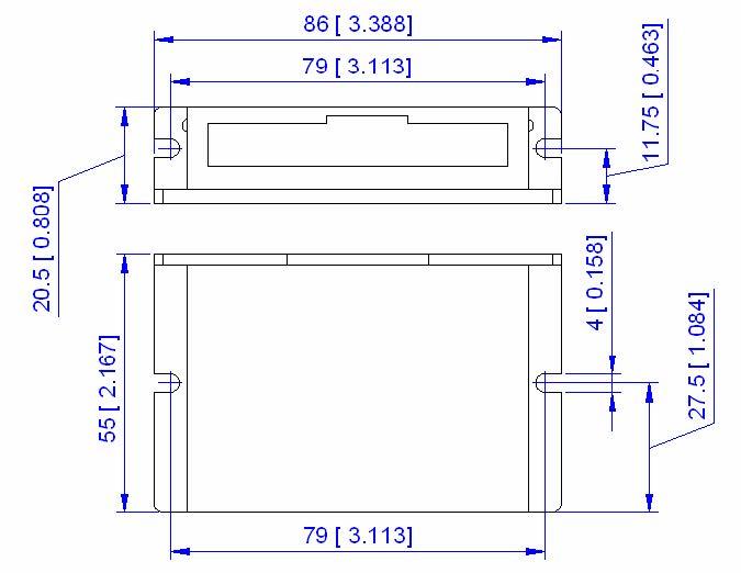
Mechanical specifications (Unit: mm, 1 inch=25.4 mm) |
||||||||||||||||||||||||||||||||||||
|
|
||||||||||||||||||||||||||||||||||||
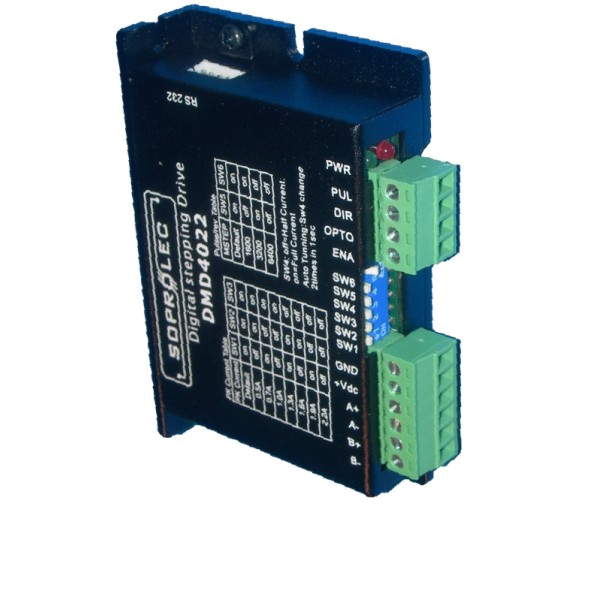
Pin assignment and description |
||||||||||||||||||||||||||||||||||||
|
|
||||||||||||||||||||||||||||||||||||
Sélection de la résolution micropas |
||||||||||||||||||||||||||||||||||||
|
Microstep resolution is specified by 5, 6 DIP switches as shown in the following table:
|
||||||||||||||||||||||||||||||||||||
Réglage du courant
|
||||||||||||||||||||||||||||||||||||
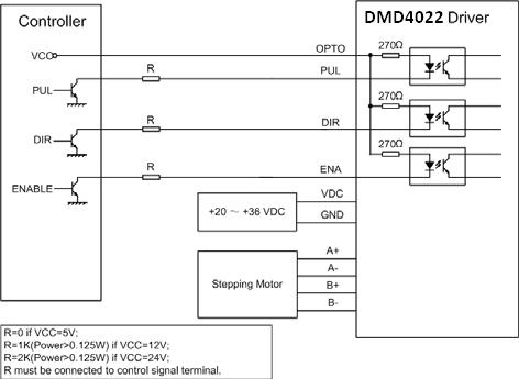
| Raccordements type | ||||||||||||||||||||||||||||||||||||
|
Figure 2: Raccordements type |
Accessories
Specifications
| Brand | Soprolec |
| Max. Voltage | 40 V |
| Max. current | 2.2 A |
| Resolution setting | DIP-switches |
| Configurable | via RS232 cable |
| Weight | 100 gr |