Specifications
|
- Intégrated heatsink and connectors.
- Input voltage: 20 to 50 VDC; Output: 0.5 to 5.6A
- Software for parameters setting on PC
- Very low noise; Low heat dissipation; very smooth movement even at low speed
- Anti-resonance system for optimum torque over the entire speed range
- Self-identification system of engine parameters for optimum operation
- "Multi-stepping" system to optimize management of micro-stepping mode and therefore reduce vibrations. The driver will thus break down the steps in an optimum manner according to the speed of rotation.
- Program resolution up to 102400 steps/rev.
- Programmable current from 0.5A to 5.6A
- Pulse input frequency up to 200KHz
- TTL-capable. Complete opto isolation
- Automatic idle-current reduction
- For use with 2 phase motors
- Compatible with PULSE/DIRECTION and CW/CCW commands
- Protection against overvoltages, overcurrents and phase errors.
- CE certification
|
|
Introduction
|
|
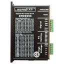
The DMD5056 driver is a new model of stepper motor driver based on DSP technology. It brings a very significant gain for the use of stepper motors and in particular, thanks to the principle of current regulation and to the breakdown of the variable steps according to the speed, it is possible to make the best use of the characteristics of your stepper motors. This technology results in optimum torque, low vibration and reduced heating.
The driver therefore makes it possible to obtain operation close to that of a DC motor even for low rotational speeds.
|
Applications
|
|
Usable with NEMA 17, 23 and 34 size motors, this driver is particularly recommended for 57CM13 and 57CM26 motors in the SOPROLEC range. Used in placement applications and XY tables, this driver will give you optimum operation with reduced noise.
Tuning by serial link allows to adjust the settings of the driver in an optimum way.
|
Electrical specifications (Tj=25℃) |
|
Parameters
|
DMD5056
|
| Min |
Typical
|
|
Unit
|
|
Output current
|
0.5
|
-
|
5.6 (4A RMS)
|
Amps
|
|
Supply voltage (DC)
|
20
|
-
|
50
|
VDC
|
|
Logic signal current
|
7
|
10
|
16
|
mA
|
|
Pulse input frequency
|
0
|
-
|
200
|
Khz
|
|
Isolation resistance
|
500
|
-
|
-
|
MΩ
|
|
|
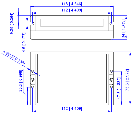
Mecanical Specifications
(Unit: mm, 1 inch=25.4 mm)
|
|
Figure 1
Mecanical Specifications
|
|
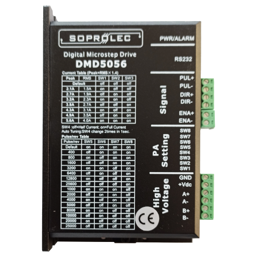
Pinout and Description
|
P1 connector
|
Pin Function
|
Details
|
|
PUL﹢(+5V)
|
Pulse signal: in single pulse (pulse/direction) mode, this input
represents pulse signal, effective for each rising edge; 4-5V when
PUL-HIGH, 0-0.5V when PUL-LOW. In double pulse mode (pulse/pulse) this
input represents clockwise (CW) pulse. For reliable response, pulse
width should be longer than 2.5us. Series connect resistance for
current-limiting when +12V or +24V used.
.
|
|
PUL- (PUL)
|
|
DIR+ (+5V)
|
DIR signal: HIGH/LOW level signal, corresponding to motor rotor
direction. For reliable response, DIR must be ahead of PUL by 5ms at
least, the initial motor direction is related with motor wiring,
exchange any set of coil can reverse motor initial direction. 4-5V when
DIR- HIGH, 0-0.5V when LOW.
|
|
DIR- (DIR)
|
|
ENA+ (+5V)
|
Enable signal: this signal is used for enabling/disabling the driver.
High level for enabling the driver and low level for disabling the
driver. Usually left unconnected (enabled).
|
|
ENA- (ENA)
|
Power connector P2 pins
|
Pin Function
|
Details
|
|
Gnd
|
DC power ground
|
|
+Vdc
|
DC power supply, +20VDC - +50VDC, Including voltage fluctuation and EMF voltage.
|
|
Phase A
|
Motor coil A (leads A+ and A-)
|
|
Phase B
|
Motor coil B (leads B+ and B-)
|
|
Microstep Resolution Selection |
|
Microstep resolution is specified by 5, 6, 7,8 DIP switches as shown in the following table:
| Microstep |
usteps/rev.( 1.8°/rev) |
SW5 |
SW6 |
SW7 |
SW8 |
| 2 |
400 |
OFF |
ON |
ON |
ON |
| 4 |
800 |
ON |
OFF |
ON |
ON |
| 8 |
1600 |
OFF |
OFF |
ON |
ON |
| 16 |
3200 |
ON |
ON |
OFF |
ON |
| 32 |
6400 |
OFF |
ON |
OFF |
ON |
| 64 |
12800 |
ON |
OFF |
OFF |
ON |
| 128 |
25600 |
OFF |
OFF |
OFF |
ON |
| 5 |
1000 |
ON |
ON |
ON |
OFF |
| 10 |
2000 |
OFF |
ON |
ON |
OFF |
| 20 |
4000 |
ON |
OFF |
ON |
OFF |
| 25 |
5000 |
OFF |
OFF |
ON |
OFF |
| 40 |
8000 |
ON |
ON |
OFF |
OFF |
| 50 |
10000 |
OFF |
ON |
OFF |
OFF |
| 100 |
20000 |
ON |
OFF |
OFF |
OFF |
| 125 |
25000 |
OFF |
OFF |
OFF |
OFF |
|
Current Setting
|
| Peak Current (A) |
RMS (A) |
SW1 |
SW2 |
SW3 |
| 1.4 |
1.0 |
OFF |
OFF |
OFF |
| 2.1 |
1.5 |
ON |
OFF |
OFF |
| 2.7 |
1.9 |
OFF |
ON |
OFF |
| 3.2 |
2.3 |
ON |
ON |
OFF |
| 3.8 |
2.7 |
OFF |
OFF |
ON |
| 4.3 |
3.1 |
ON |
OFF |
ON |
| 4.9 |
3.5 |
OFF |
ON |
ON |
| 5.6 |
4.0 |
ON |
ON |
ON |
|
|
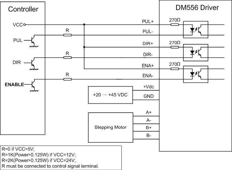
Typical Connections
|
|
|
| Figure 2: Typical connections |
![[2CM560] 2CM560 Digital stepper driver - 50V 6A Kinco](/web/image/product.product/1919/image_128/%5B2CM560%5D%202CM560%20Digital%20stepper%20driver%20-%2050V%206A%20Kinco?unique=3360e07)
![[EM556S] EM556S Digital stepper driver - 50V 5.6A Leadshine](/web/image/product.product/1874/image_128/%5BEM556S%5D%20EM556S%20Digital%20stepper%20driver%20-%2050V%205.6A%20Leadshine?unique=edb2ae4)