Features
|
| |
- Patented Technology
- Low cost
- High torque, even at high speed
-
Input voltage 20-48VDC
-
Automatic idle-current reduction (configurable)
- For use with 2 or 4 phases motors (unipolar or bipolar)
- Opto-isolated input signals
-
Pulse input frequency up to
100 KHz
-
16 selectable micro-step resolutions of 400-25,600 via DIP switches
-
8 selectable output current settings of 1.8 – 5.6A via DIP switches
- Step & direction (PUL/DIR) control
-
Protections for over-voltage, over-current and short circuits
-
Small size (118x75.5x33mm)
-
Removable terminal blocks
|
|
Introduction
|
|
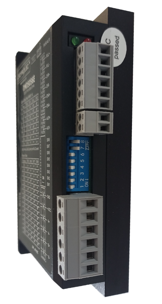
The DMD5056E is a digital stepper drive with simple design and easy
setup. This stepper drive is able to power 2-phase and 4 phase stepper motors
smoothly with optimal torque and low motor heating & noise. Its
operating voltage is 20-48VDC and it can output up to 5.6A current. All
the micro step and output current are done via DIP switches. Therefore,
the DMD5056E is the ideal choice for applications requiring simple step
& direction control of NEMA 23,24 and 34 stepper motors.
|
Applications
|
|
The DMD5056E stepper drive is designed to power 2 phase (1.8°) or 4-phase
(0.9°) NEMA 23, 24, and 34 stepper motors. It can be easily
adopted in many industries (CNC, medical, automation, packaging…), such
as X-Y tables, engraving machines, labeling machines, mills, plasma,
laser cutters, pick and place devices, and so on. Its excellent
performance, simple design, and easy setup make it ideal for many step
& direction control type applications.
|
Electrical specifications
(Tj=25℃) |
|
Parameters
|
DMD5056E
|
|
Min.
|
Typical |
Max
Unité
|
|
Output current
|
1.8
|
-
|
5.6 (4A RMS)
|
Amps
|
|
Supply Voltage(DC)
|
20
|
24-48
|
50
|
VDC
|
|
Logic signal current
|
7
|
10
|
16
|
mA
|
|
Pulse input frequency
|
0
|
-
|
100
|
Khz
|
|
Insulation resistance
|
500
|
-
|
-
|
MΩ
|
|
| Mecanical specifications
(Unité: mm, 1 inch=25.4 mm) |
|
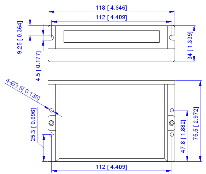
Figure 1:
Mecanical specifications
|
Pinout and Description
|
P1 Connector
|
Pin Function
|
Details
|
|
PUL﹢(+5V)
|
PULSE signal: In single pulse (pulse/direction) mode, this input represents pulse signal, each rising or falling edge active (software configurable); 4-5V when PUL-HIGH, 0-0.5V when PUL-LOW. In double pulse mode (pulse/pulse) , this input represents clockwise (CW) pulse,active both at high level and low level (software configurable). For reliable response, pulse width should be longer than 2.5μs. Series connect resistors for current-limiting when +12V or +24V used. The same as DIR and ENA signals.
|
|
PUL- (PUL)
|
|
DIR+ (+5V)
|
DIR signal: In single-pulse mode, this signal has low/high voltage levels, representing two directions of motor rotation; in double-pulse mode (software configurable), this signal is counter-clock (CCW) pulse,active both at high level and low level (software configurable). For reliable motion response, DIR signal should be ahead of PUL signal by 5μs at least. 4-5V when DIR-HIGH, 0-0.5V when DIR-LOW. Please note that rotation direction is also related to motor-Driver wiring match. Exchanging the connection of two wires for a coil to the Driver will reverse motion direction.
|
|
DIR- (DIR)
|
|
ENA+ (+5V)
|
Enable signal: This signal is used for enabling/disabling the Driver. High level (NPN control signal, PNP and Differential control signals are on the contrary, namely Low level for enabling.) for enabling the Driver and low level for disabling the Driver. Usually left UNCONNECTED (ENABLED).
|
|
ENA- (ENA)
|
P2 Power connector
|
Pin Fonction
|
Details
|
|
Gnd
|
Power ground
|
|
+V
|
Power supply, 20~45 VDC, Including voltage fluctuation and EMF voltage.
|
|
Phase A
|
Motor phase A (A+ and A- wires)
|
|
Phase B
|
Motor phase B (B+ and B- wires)
|
|
|
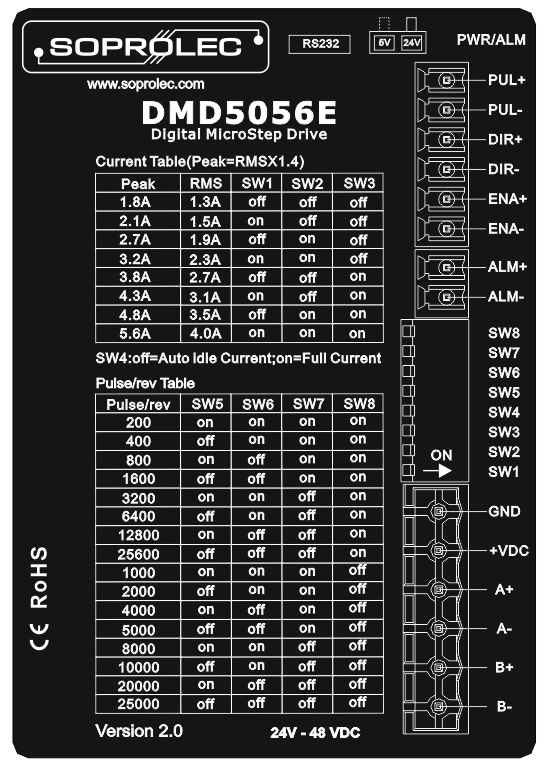
Microstep Resolution Selection
|
|
When it’s not in software configured mode, microstep resolution is set by SW5, 6, 7, 8 of the DIP switchas shown in the following table:
| Microstep |
usteps/rev.( 1.8°/rev) |
SW5 |
SW6 |
SW7 |
SW8 |
| 2 |
400 |
OFF |
ON |
ON |
ON |
| 4 |
800 |
ON |
OFF |
ON |
ON |
| 8 |
1600 |
OFF |
OFF |
ON |
ON |
| 16 |
3200 |
ON |
ON |
OFF |
ON |
| 32 |
6400 |
OFF |
ON |
OFF |
ON |
| 64 |
12800 |
ON |
OFF |
OFF |
ON |
| 128 |
25600 |
OFF |
OFF |
OFF |
ON |
| 5 |
1000 |
ON |
ON |
ON |
OFF |
| 10 |
2000 |
OFF |
ON |
ON |
OFF |
| 20 |
4000 |
ON |
OFF |
ON |
OFF |
| 25 |
5000 |
OFF |
OFF |
ON |
OFF |
| 40 |
8000 |
ON |
ON |
OFF |
OFF |
| 50 |
10000 |
OFF |
ON |
OFF |
OFF |
| 100 |
20000 |
ON |
OFF |
OFF |
OFF |
| 125 |
25000 |
OFF |
OFF |
OFF |
OFF |
|
|
Dynamic current setting
|
| Peak Current (A) |
RMS (A) |
SW1 |
SW2 |
SW3 |
| 1.8 |
1.3 |
ON |
ON |
ON |
| 2.1 |
1.5 |
OFF |
ON |
ON |
| 2.7 |
1.9 |
ON |
OFF |
ON |
| 3.2 |
2.3 |
OFF |
OFF |
ON |
| 3.8 |
2.7 |
ON |
ON |
OFF |
| 4.3 |
3.1 |
OFF |
ON |
OFF |
| 4.9 |
3.5 |
ON |
OFF |
OFF |
| 5.6 |
4.0 |
OFF |
OFF |
OFF |
SW4 OFF : current is recduced by 50% one second after motor stops.
SW4 ON : current is always at maximum.
|
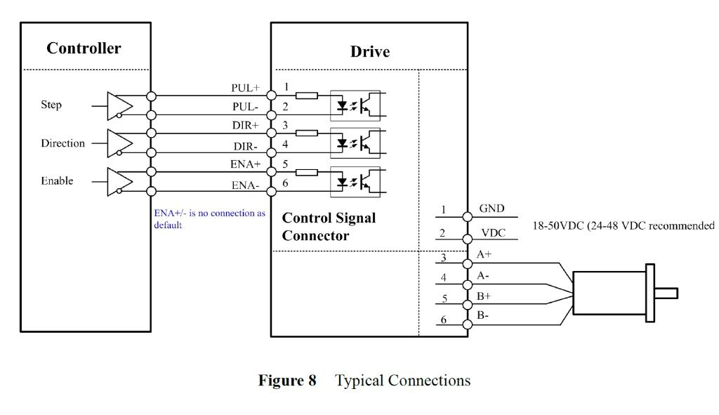
Typical connections
|

![[2CM560] 2CM560 Digital stepper driver - 50V 6A Kinco](/web/image/product.product/1919/image_128/%5B2CM560%5D%202CM560%20Digital%20stepper%20driver%20-%2050V%206A%20Kinco?unique=3360e07)
![[DMD5056] DMD5056 digital stepper driver - 50V / 5.6A](/web/image/product.product/1853/image_128/%5BDMD5056%5D%20DMD5056%C2%A0digital%20stepper%20driver%20-%2050V%20-%205.6A?unique=d79d230)
![[EM556S] EM556S Digital stepper driver - 50V 5.6A Leadshine](/web/image/product.product/1874/image_128/%5BEM556S%5D%20EM556S%20Digital%20stepper%20driver%20-%2050V%205.6A%20Leadshine?unique=edb2ae4)