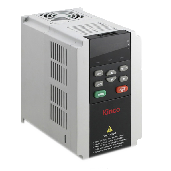
Kinco FV100 frequency inverter - Modbus - Single phase
Frequency inverter
Voltage: 220V
Output frequency: 0 - 300Hz
Frequency control: Keyboard, analog, Pulses, RS485
2 analog outputs (0/4 - 20mA or 0/2 - 10V)
1 pulse output
1 bi-directional open collector output
1 Output on Relay
2 analog inputs
1 Differential input
7 Digital Inputs
1 RS485 port
Frequency Inverter FV100 Series
Puissances : 750W - 2200W, et 3700W (4T)
Carrier Frequency up to 15kHz
Output Frequency : 0 - 300Hz
Auto torque boost and auto slip compensation function
Vectoriel control with or without PG
Wall mounting
1 RS485 Modbus port
1 10v reference voltage output
3 analog input -10~+10V
7 digital multi-function input, Optocoupler isolation, include 1 pulse input
2 analog output 0~10V or 0/4~20mA
1 optocoupled output, open collector 30V - 50mA
1 pulse open collector output
1 relay output, 250VAC - 2A, 30VDC - 1A
1 power supply output +24V - 200 mA
External dimension:
W: 115 mm
H : 185 mm
D: 171 mm
Weight: 2 kg
Features
| Item | Description | |
|---|---|---|
| Input | Rated voltage and frequency | 4T : triphase 380V~440V – 50Hz/60Hz // 2S : singlephase 200V~240V |
| Allowable voltage range | 4T : 320V~460V – 2S : 180V~260V - Voltage unbalancedness <3 % - Frequency +-5 % | |
| Output | Rated Voltage | 0~Rated input voltage |
| Frequency | 0Hz~300Hz (0Hz~3000Hz custom) | |
| Overload capacity | Type G : 150 % 1 mn – 180 % 10 s | |
| Controle method | Vector control without PG. | Vector control with PG. V/F control |
| Modulation System | Space vector PWM modulation | |
| Starting torque | 0.5Hz : 150 % of rated torque(Vector control without PG) – 0.5Hz : 200 % of rated torque(vector control with PG) | |
| Frequency accuracy | Digital setting : max. frequency x +- 0.01% – Analog setting : max. frequency x +-0.2 % | |
| Frequency resolution | Digital setting : 0.01Hz – Analog setting : max. frequency x 0.05 % | |
| Torque boost | Manual torque boost : 0% ~ 30.0 % | |
| V/F patterns | 4 patterns : 1 V/F curve mode set by user and 3 patterns are drop torque characters curve (2.0 power - 1.7 power - 1.2 power) | |
| Acc/Dec curves | Linear/deceleration. Four kinds of acceleration/deceleration time | |
|
DC braking Auto current limit |
Braking starting frequency : 0.00~60.00Hz – Braking Time 0.0~10.0s – Braking current : 0.0~100.0 % Limit current during operation automatically to prevent frequent overcurrent trip |
|
| Customized function | Jogging | Jogging frequency range : 0.00Hz~50.00Hz. Jogging acceleration/deceleration time : 0.1~60.0s |
| Multiple speed operation | Implement multiple speed operation by digital inputs | |
| Operation functions | Operation command | Keypad setting – Terminal setting – Communication setting |
| Frequency command | Keypad setting – Terminal setting – Communication setting – Pulse input | |
| Auxiliary frequency setting | Implement flexible auxiliary frequency trim and frequency synthesis | |
| Analog output | 2 channel analog output (0/4~20mA or 0/2~10V) | |
| Led display | LED display | About 20 parameters : display setting frequency – output frequency – output voltage – output current… |
| Parameters copy | Copy parameters by operation panel | |
| Keys lock and function selection | Lock part of keys or all the keys. Define the function of part of keys | |
| Protection functions | | Overcurrent protection - overvoltage protection – undervoltage protection – overheat protection – overload protection – open phase protection (selectable) and so on |
| Environnement | Use | Indoor - installed in the environnement free from direct sunlight – dust – corrosive gas – combustible gas – oil mist – steam and drip |
| Altitude | Derated above 1000m – the rated output current shall be decreased by 10% for every rise of 1000m | |
| Ambient temperature | -10°C~40°C - derated at 40°C~50°C | |
| Humidity | 5%~95%RH – non-condensing | |
| Vibration | Less than 5.9m/s2 (0.6g) | |
| Storage temperature | -40°C~70°C | |
| Structure | Protection Class | IP20 |
| Cooling method | Air cooling with fan control | |
| Installation method | Wall mounting | |
| Efficiency | ≥ 93 % | |
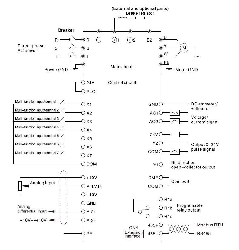
Entrées / Sorties
| Category | Marking | | Description |
|---|---|---|---|
| GND for the shield | PE | GND for the shield | |
| Communication | RS+ / RS- | port RS485 | Use twisted-pair or shield cable |
| Analog input | AI1 and AI2 | Analog single-ended | Analog voltage or current input – mode selected by jumpers AI1/AI2 (Reference ground : GND) ) – Voltage range -10V~+10V (Input resistor 45kOhm) Resolution 1/4000 – Current range 0mA~20mA Resolution 1/2047 (jumper select) |
| AI3+ | Analog voltage differential input A3+ or analog voltage single-ended input | When connected to the analog voltage differential : input AI3+ is the same phase input and AI3- the inverted input – When connected to the analog voltage single-ended input : AI3+ is signal input and AI3- is GND(Reference ground : GND) - Voltage range -10V~+10V (Input resistor 15kOhm) Resolution 1/4000 | |
| AI3- | Analog voltage differential input A3- or analog voltage single-ended input | ||
| Analog output | A01 and AO2 | | Providing analog voltage or current selected by jumper AO1/AO2 – The default setting is output voltage - Voltage range 0V~10V – Current range 0/4mA~20mA |
| Multifonction input terminal | X1~X6 | Multifonction input terminal | Can be defined as multi-function digital input terminal – Optocoupler isolation input – input resistor 3.3kOhm – Maximum input frequency of X1~X6 : 200kHz Maximum input frequency of X7 : 100kHz - Input voltage range: 2~30V |
| X7 | Multifonction input terminal or pulse input | | |
| Multifonction output terminal | Y1 | Bi-direction open collector output | Can be defined as multi-function digital ouput terminal (Com port : CME) – Optocoupler isolation output – Max. working voltage : 30V max. Current 50mA |
| Y2 | Open collector pulse output terminal | Can be defined as multi-function digital pulse signal ouput terminal (Com port : COM) – Maximum output frequency : 100kHz | |
| Power supply | 10 | +10V power supply | Reference Voltage +10V – 5mA |
| GND | | GND for analog signal and +10 power supply – Internal isolation from COM and CME | |
| 24V | +24V power supply | for small equipments 24V 200mA max. | |
| Common port | PLC | Mult-ifunction input common port | Common port of X1~X7 (shortcut with 24V in default) PLC is isolated from 24V internally |
| COM | Common port of 24V power supply | 3 Common ports in all cooperate with other terminals – COM is isolated from CME and GND internally | |
| CME | Y1 output common port | | |
|
Relay Output terminal 1 |
R1a R1b R1c |
| Can be defined as multi-function relay output terminal – R1a-R1b : normally closed / R1a-R1c : normally open / Contact capacity : AC250V/2A (cos = 1) AC250V/1A (cos = 0.4) DC30V/1A |
| | | ||
| | |
Specifications
| Drive power | 750 W or 2200 W |