CS2RS-D507 Modbus stepper driver - 50V/7A - Closed loop
Driver for 2 phase stepper motor
CS-M... series (with 1000 to 5000 ppr encoder).
1.0 to 7A / 20 to 50 VDC
Closed loop
Modbus RTU bus (RS485)
8 switches for ID configuration
7 programmable inputs
3 programmable outputs
Tuning on PC via RS232 link
Product Documents
Internal Reference:
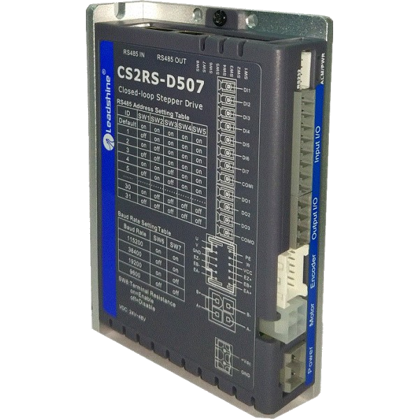
CS2RS-D507
CS2RS-D507 digital microstep driver
|
||||||||||||||||||||||||||||||||||||||||||||||||||||||||||||||||||||||||||||||||||||||||||||||||||||||||||||||||||||||||||||||||||||||||||||||||||||||||||||||||||||||||||||||||||||||||||||||||||||||
| Introduction | ||||||||||||||||||||||||||||||||||||||||||||||||||||||||||||||||||||||||||||||||||||||||||||||||||||||||||||||||||||||||||||||||||||||||||||||||||||||||||||||||||||||||||||||||||||||||||||||||||||||
| The CS2RS series offers closed-loop stepper drivers based on the standard Modbus RTU protocol, using RS485 communication to network up to 31 axes, built-in PR function with 16-segment position table (PR mode). They can not only solve the problem of step loss in the open-loop stepper system, but also avoid the need for additional controllers in most point-to-point applications, to greatly improve the system reliability and reduce the costs. The CS2RS series also supports teach function, position profile, velocity profile and homing operation modes. |
||||||||||||||||||||||||||||||||||||||||||||||||||||||||||||||||||||||||||||||||||||||||||||||||||||||||||||||||||||||||||||||||||||||||||||||||||||||||||||||||||||||||||||||||||||||||||||||||||||||
| Applications | ||||||||||||||||||||||||||||||||||||||||||||||||||||||||||||||||||||||||||||||||||||||||||||||||||||||||||||||||||||||||||||||||||||||||||||||||||||||||||||||||||||||||||||||||||||||||||||||||||||||
|
Usable with NEMA 17, NEMA 23 and 34 size motors, this driver is particularly recommended for 2-phase motors of the CS-M... series of the SOPROLEC range, having an integrated encoder with a resolution of 1000 to 5000 pulses per revolution. Parameter setting via RS232 serial link allows the driver settings to be adjusted optimally. |
||||||||||||||||||||||||||||||||||||||||||||||||||||||||||||||||||||||||||||||||||||||||||||||||||||||||||||||||||||||||||||||||||||||||||||||||||||||||||||||||||||||||||||||||||||||||||||||||||||||
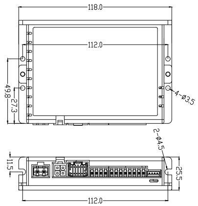
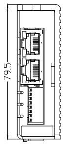
| Mechanical specifications (Unit: mm, 1 inch=25.4 mm)Dimensions: 118*79.5*25.5 mm Weight: 0.65 kg Operating temperature: 0-50℃ (32F – 122F) Storage temperature: -20℃-65℃ (-4F – 149F) Tolerated humidity: 40-90%RH Vibrations tolerated: 10-55Hz/0.15mm Mounting: Vertical or Horizontal |
||||||||||||||||||||||||||||||||||||||||||||||||||||||||||||||||||||||||||||||||||||||||||||||||||||||||||||||||||||||||||||||||||||||||||||||||||||||||||||||||||||||||||||||||||||||||||||||||||||||
|
|
||||||||||||||||||||||||||||||||||||||||||||||||||||||||||||||||||||||||||||||||||||||||||||||||||||||||||||||||||||||||||||||||||||||||||||||||||||||||||||||||||||||||||||||||||||||||||||||||||||||
Pin assignment and description |
||||||||||||||||||||||||||||||||||||||||||||||||||||||||||||||||||||||||||||||||||||||||||||||||||||||||||||||||||||||||||||||||||||||||||||||||||||||||||||||||||||||||||||||||||||||||||||||||||||||
|
CN1 - Input Power Connector
|
||||||||||||||||||||||||||||||||||||||||||||||||||||||||||||||||||||||||||||||||||||||||||||||||||||||||||||||||||||||||||||||||||||||||||||||||||||||||||||||||||||||||||||||||||||||||||||||||||||||
|
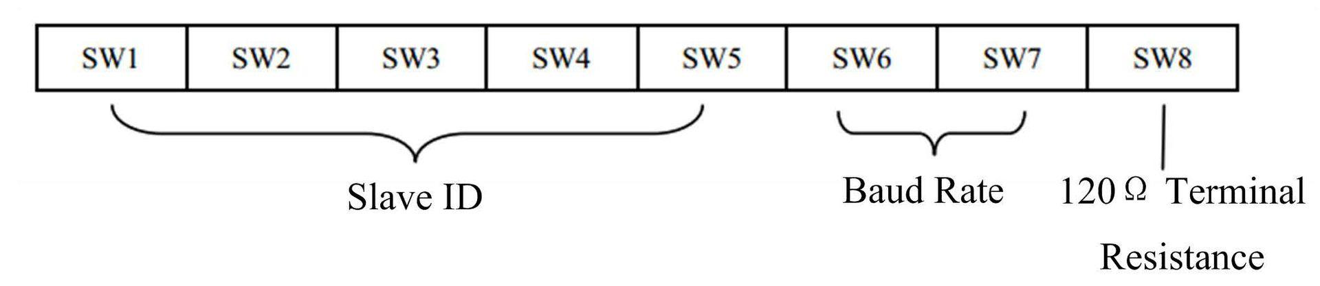
DIP Switches
|
||||||||||||||||||||||||||||||||||||||||||||||||||||||||||||||||||||||||||||||||||||||||||||||||||||||||||||||||||||||||||||||||||||||||||||||||||||||||||||||||||||||||||||||||||||||||||||||||||||||
|
Configuration of the slave position of the driver: SW1 to SW5
|
||||||||||||||||||||||||||||||||||||||||||||||||||||||||||||||||||||||||||||||||||||||||||||||||||||||||||||||||||||||||||||||||||||||||||||||||||||||||||||||||||||||||||||||||||||||||||||||||||||||
| Baud Rate : SW6 -SW7 |
||||||||||||||||||||||||||||||||||||||||||||||||||||||||||||||||||||||||||||||||||||||||||||||||||||||||||||||||||||||||||||||||||||||||||||||||||||||||||||||||||||||||||||||||||||||||||||||||||||||
|
||||||||||||||||||||||||||||||||||||||||||||||||||||||||||||||||||||||||||||||||||||||||||||||||||||||||||||||||||||||||||||||||||||||||||||||||||||||||||||||||||||||||||||||||||||||||||||||||||||||
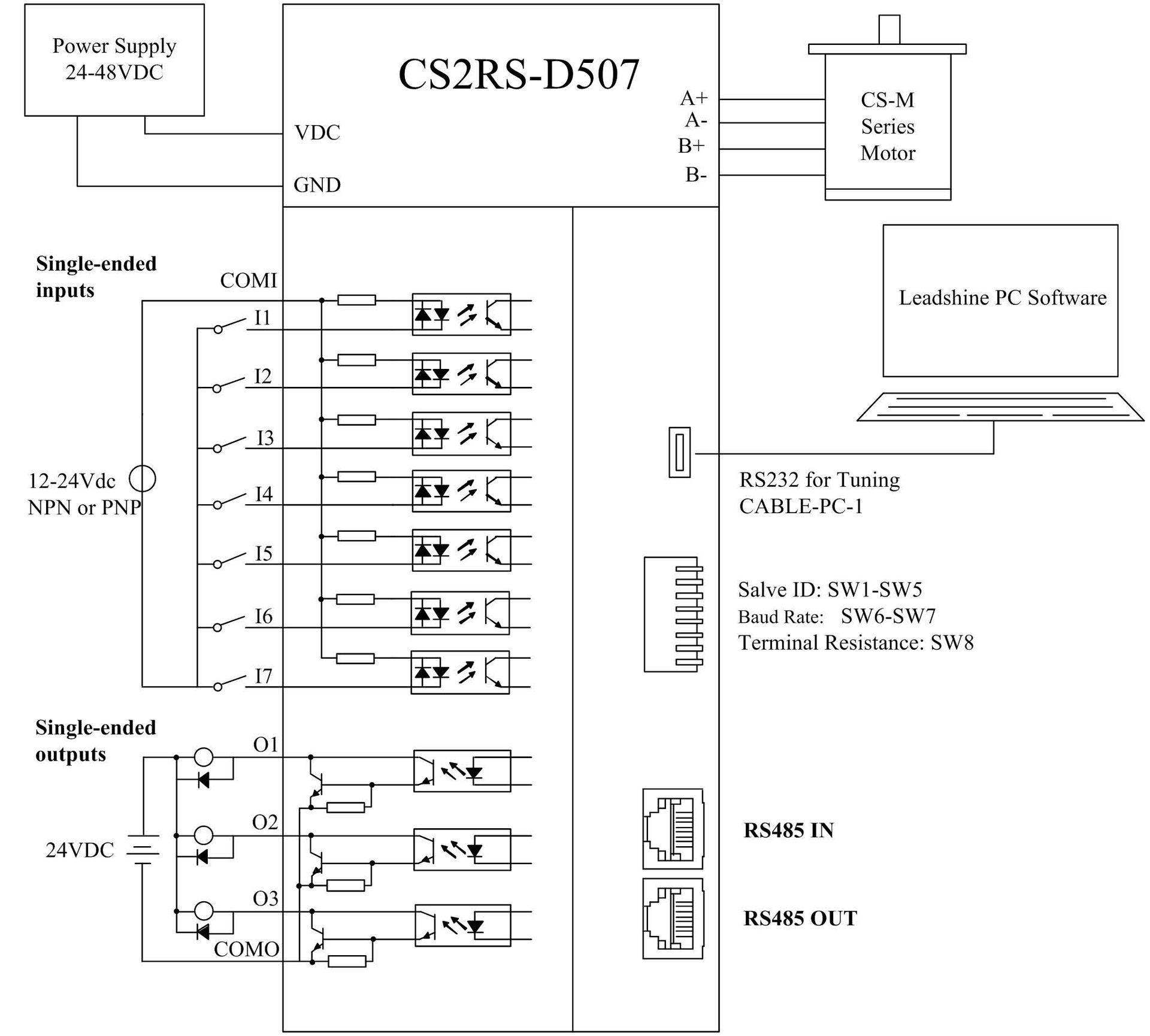
Typical Connections |
||||||||||||||||||||||||||||||||||||||||||||||||||||||||||||||||||||||||||||||||||||||||||||||||||||||||||||||||||||||||||||||||||||||||||||||||||||||||||||||||||||||||||||||||||||||||||||||||||||||
|
Logiciel de paramétrage Leadshine Motion Studio V1.49 :
https://www.leadshine.com/upfiles/downloads/4f2e3904b60df00acb75d9cd2ae65491_1702632536136.zip
Accessories
Specifications
| Brand | Leadshine |
| Inputs | 7 |
| Outputs | 3 |
| Min. Voltage | 24 V |
| Max. Voltage | 50 V |
| Max. current | 7 A |
| Resolution setting | Tuning software |
| Configurable | via RS232 cable |
| Interface | Modbus RS485 |
| Current setting | Tuning software |